2.2 Control Signal
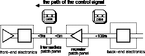
The path of the control signal
from the back-end electronics to the front-end electronics can be separated
into five consecutive parts - see
Figure
2.41:
-
the back-end electronics - the generation of
the control signals,
-
the way to the repeater patch panels - the transmission
of signal and the signal filter,
Figure 2.41 Schematic way of the
control signal from the back-end electronics to the front-end electronics.
 |
-
the repeater patch panel - the amplification
and restoration of the signal and the transmission of the signal on board,
-
the way to the front-end electronics - the intermediate
patch panels and the transmission to the front-end electronics
-
the front-end electronics - the processing and
distribution of the control signals.
2.2.1 Back-End Electronics
The second function of the
back-end electronics - in addition to the data handling - is to control
the front-end electronics. A separate VME-9U module - the TRT-TTC (trigger,
timing, and control) implements this. It communicates with the ATLAS-TTC
system, extracts the timing information, and after a proper delay adjustment
transmits them to the front-end. In addition it provides the TTC information
to the RODs of the crate through a dedicated backplane. It also controls
the parameter-control link which allows one to read and write parameters
and to transmit synchronous commands to the front-end.
The signals which have to be
distributed to the front-end electronics are:
-
the LHC clock (BC) - a 40 MHz clock signal synchronized
to the bunch crossing in ATLAS,
-
the level-1 trigger signal (L1A) - a trigger
signal which validates an event,
-
the test pulse - a timing signal used in the
front-end electronics to create a test pulse which is capacitively coupled
to the input of the ASDBLR,
-
the bunch counter reset (BCR) - a timing signal
to reset the bunch counter of the DTMROC,
-
the event counter reset (ECR) - a timing signal
to reset the event counter of the DTMROC,
-
the front-end hard reset - a timing signal to
reset the DTMROC,
-
and data signals to write and read the control
information to the DTMROC.
The transmission of these
signals is carried out with LVDS levels over four differential pairs:
-
the clock (BX) - 40 MHz LVDS clock,
-
the hard-reset - 40 Mbit/s LVDS signal,
-
a write control, which has encoded L1A, BCR,
ECR and the control information to set the DTMROC - 40 Mbit/s "random"
LVDS signal,
-
and a read control, for the read out of the
settings - 40 Mbit/s "random" LVDS signal.
For signal integrity, the
last line can be handled like a data line - see
Chapter
2.1.
As mentioned before, the readout
segmentation does not follow the mechanical segmentation of the detector.
In particular, in the end-cap, a readout slice involves all the wheels.
It is therefore impossible to have the same segmentation for the timing
signal as for the readout with a precision of the order of 1 ns. Therefore
the timing and the parameter control signals will be distributed to subsets
of 1/32 of each end-cap wheel and 1/32 of each barrel module. Each single
line can be delayed separately to achieve accurate timing. Consequently,
phase shifts due to different cable lengths are intercepted at the beginning
of the transmission line.
2.2.2 Transmission
to the Repeater Patch Panels
For the way from the back-end
electronics to the repeater patch panel, the control lines follow the path
of the data lines but in opposite direction - see
Chapter
2.1.6. The 40-Mbit/s control signals behave like the data signal. The
compensation network can be placed on both ends of the cable, although
it provides a better signal to noise ratio when placed at the receiving
end.
The 40-MHz clock shows a slightly
different behavior. Expressed in transmission rates, it is a 80-Mbit/s
signal of consecutive "01"s. On one hand, it doubles the transmission rate
on the other hand its symmetric structure opens the eye plot. Thus the
low frequency distortion of the cable becomes negligible and no compensation
filter is necessary for the clock signal.
2.2.3 Repeater Patch
Panels
At the level of the repeater
patch panels, the control signals have to be fanned out because one subset
of control lines from the back end has to supply several groups of front-end
boards - see
Chapter
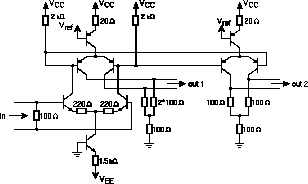
2.2.5. Hence a repeater needs one differential input and two differential
outputs. This could either be achieved by a single comparator or a LVDS
receiver which provides its TTL signal to two LVDS drivers or by using
a second output stage in a transistor network - see
Figure
2.42
Figure 2.42 Schematic drawing
[44]
of a LVDS repeater based on HF3XXX with 2 outputs.
 |
The chosen solution will be
either to integrate a second output in the bipolar ASIC to be developed
or to use two repeaters with single outputs which are connected to the
same input signal.
Due to the different granularity
of the barrel and the end-cap, the PC boards for the repeater patch panels
are different. The same guide lines as discussed in Chapter
2.1 have to be obeyed to integrate signal integrity into the design
of these boards.
2.2.4 Transmission
to the Front-End Electronics
For the way from the repeater
patch panel to the front-end electronics, the control lines follow again
the path of the data lines but in opposite direction - see
Chapter
2.1.4.
2.2.5 Front-End Electronics
At the front-end boards, all
DTMROCs of one timing region of interest have to be supplied by a subset
of control/timing signals. These regions of interest are one half of each
module for the barrel and 1/32 of each wheel for the end cap. Hence, the
granularity is:
-
inner (outer) half of the inner barrel module
1 - 10 (11) DTMROCs,
-
inner (outer) half of the middle barrel module
2 - 15 (18) DTMROCs,
-
inner (outer) half of the outer barrel module
3 - 25 (25) DTMROCs,
-
1/32 of the end-cap wheel A - 6*4 = 24 DTMROCs,
-
1/32 of the end-cap wheel B - 3*4 = 12 DTMROCs,
-
1/32 of the end-cap wheel C - 6*3 = 18 DTMROCs.
This kind of granularity means
two kinds of drawbacks. Each DTMROC connected to the transmission line
adds a capacitive load, and as the DTMROCs are spread all over the front-end
boards, the skew of the timing signals from the first to the last DTMROC
can become substantial.
Figure 2.43 TTC distribution to the DTMROCs:
the signals are routed in a daisy chain from one chip to the next one and
terminated at the end of the chain.
 |
The signals have to be routed
in a daisy chain in order to avoid reflections at stubs. Each input of
the DTMROC is a capacitive load and degrades the transmitted signal. The
capacitive load reflects the signal with a reflection coefficient of
 .
.
Thus, the reflected signal
is for low frequencies the negative derivation of the incoming signal -
e.g. a negative bump for the rising edge of the signal. The signal transmitted
through the capacitive load is given by the transmission coefficient

which is the equation for
a low-pass filter - the rise time of the signal increases. In addition,
the capacitive load Cload adds to the distributed capacitance C0 of the
transmission line and effects its wave impedance
 .
.
To estimate these effects for
the barrel, a prototype of the inner module like seen in Figure
2.16 was equipped with 11 10-pF capacitors to simulate 22 DTMROCs with
an input capacitance of about 5 pF. The first capacitor was supplied over
10 m of the AWG-36 STP cable. The last capacitor was terminated by a 100-Ohm
resistor. Each DTMROC will see depending on its position in the transmission
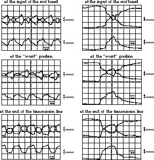
line different signals which are nearly acceptable at the termination point
but not usable at other positions - see Figure
2.44.
Figure 2.44 Screen shots of the
signal distortion due to capacitive loads on the transmission line for
a clock signal of 40 MHz (left) and a single impulse of 25 ns (right):
22 DTMROCs are simulated by 11 10-pF capacitors on the inner barrel module;
the signal is fed to the first capacitor through 10 m of the AWG-36 STP
cable; the last capacitor is terminated by a 100-Ohm resistor; the signals
are distorted by the multiple reflections on the capacitive loads.
 |
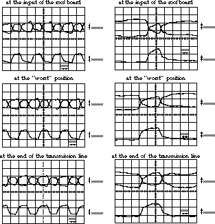
Tuning the multiple reflections
by changing the termination resistor allowed one to improve the situation
- see Figure
2.45. Replacing the 100-Ohm resistor by a 50-Ohm resistor approves
the theory behind formula (2.35),
but the estimation of Cload is difficult as it depends not only on the
values of the capacitive load but also on its position in the transmission
line. However, this formula does not include the effect of improving the
signal transmission by strategical mis-termination using multiple reflections.
Figure 2.45 Screen shots of the
signal distortion due to capacitive load of the transmission line for a
clock signal of 40 MHz (left) and a single impulse of 25 ns (right): 22
DTMROCs are simulated by 11 10-pF capacitors on the inner barrel module;
the signal is fed to the first capacitor through 10 m of the AWG-36 STP
cable; the last capacitor is terminated by a 50-Ohm resistor; the signals
are distorted by the multiple reflections on the capacitive loads.
 |
Other measurements simulating
the future end-cap distribution showed equal results. The same timing signals
have to provide six front-end boards each holding four DTMROCs in the worst
case for wheel type A. Thus, the front-end boards were mimicked each by
four 4.7-pF capacitors interconnected by 10 cm of AWG36 STP cable. The
first group was fed by 10 m of the same cable - see Figure
2.46.
Figure 2.46 Principle schematics
of the simulation of the TTC distribution for the end cap: 10 m of AWG36
STP cable feed 6 groups of 4 4.7-pF capacitors mimicking front-end boards
which are connected by 10 cm of AWG36 STP cable.
 |
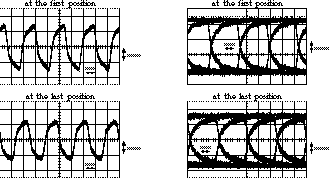
The last group had to be terminated
by 75 Ohm to get the best results - see Figure
2.47.
Figure 2.47 Eye plots of the signal
distortion due to capacitive load for the end-cap for a clock of 40 MHz
(left) and a random signal of a bit rate of 40 Mbit/s: 10 m of AWG36 STP
cable feed 6 groups of 4 4.7-pF capacitors mimicking front-end boards which
are connected by 10 cm of AWG36 STP cable.
 |
One drawback is that the skew
from the first DTMROC to the last DTMROC is up to 5 ns. Therefore it was
decided to limit the number of DTMROCs which are provided by the same transmission
line to about 12. This doubles the number of necessary twisted pairs for
the TTC distribution, and the repeaters on the repeater patch panel has
to fan out the necessary outputs - see Chapte
2.2.3.
Hence, the granularity changes
to:
-
inner (outer) half of the inner barrel module
1 - 10 (11) DTMROCs,
-
half of inner (outer) half of the middle barrel
module 2 - 7/8 (9) DTMROCs,
-
half of inner (outer) half of the outer barrel
module 3 - 12/13 DTMROCs,
-
half of 1/32 of the end-cap wheel A - 3*4 =
12 DTMROCs,
-
1/32 of the end-cap wheel B - 3*4 = 12 DTMROCs,
-
half of 1/32 of the end-cap wheel C - 3*3 =
9 DTMROCs.


 .
.
 .
.