


| CERN -> ATLAS -> TU Vienna | ||
   |
High-Density Digital Links |  |
Due to the huge amount of data and the large extend of the TRT, careful design and good knowledge of the system is essential to perform the tasks of signal integrity and electromagnetic compatibility. Therefore this chapter describes the TRT starting from the generation of the signal, the processing and transmission, to the mechanical structure and the services of the system.
| signal generation |
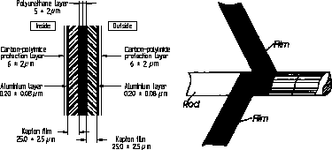
The basic detecting element in the TRT is a straw detector [6]. A straw is a tube of a diameter of 4 mm which builds the cathode of the system. It is made from a polyimide film (kapton) coated with a conductive layer on one side and an insulating layer on the other. Two tapes of this film are wound together in spirals to create the final straw - see Figure 1.5. The straws are reinforced by four carbon-fibre strands, which are glued along the straws.
 |
A gold-plated tungsten-wire with a diameter of 30 um builds the anode inside each tube. The straw is filled with a special Xe-gas mixture of 70% Xe, 20% CF 4 , and 10% CO 2 . A high voltage of 1.6 kV creates a static electric field between the wire and the metallized tube wall.
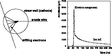 |
When a charged particle traverses the straw, it ionizes the gas and the electrons start to drift towards the wire while the positive ions drift towards the cathode. An avalanche is produced as the electron accelerates very near the wire surface. This avalanche creates a pulse at the end of the straw - see Figure 1.6.
The signal contains a fast electron component of only 3 to 5% of the total charge and a large very-slow-ion component. In order to avoid shifts of the baseline for the read-out electronics, these ion tails have to be eliminated in the front-end electronics by analogue signal processing.
In addition the TRT is a Transition-Radiation detector. Radiation is emitted when a particle moves across the interface of two media with different dielectric constants. For charged relativistic particles like fast travelling electrons, this radiation consists of X-rays.
In the TRT foam and foils are used to produce the interfaces. The transition X-rays interact in the gas of the straw tubes and produce much larger pulses than traversing charged particles. Thus, two discriminator thresholds will distinguish among different kinds of particles: a low-energy threshold around 200 eV to detect minimum-ionizing particles and a high-energy threshold around 6 keV for pulses created by the transition-radiation effect.
| signal pre-processing |
The signal deriving from the straws carries two kinds of information: first the amplitude determines the effect which produced the signal (ionization or transition radiation); second the arrival time gives the impact point of the particle into the straw.
To obtain this data, the signal has to be amplified and the previously-mentioned ion tail to be removed. Discriminators compare the shaped signal with thresholds for the two kind of particles. Obtaining the timing information allows to recalculate the position of the impact of the particle into one straw. The information about the particle and the timing is stored in a pipeline.
Not all the information which is gathered inside the TRT is worthwhile for physics. Thus only the data which corresponds to special events indicated by trigger signals are sent out of the detector.
| signal transmission |
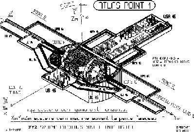
The digital information has to be transferred out of the detector to the service cavern USA 15 - see Figure 1.7. For this purpose, it has to pass through the calorimeters and the muon spectrometer, where it should not interfere with their associated electronics. After about 100 m the signal arrives at the post-processing electronics. For maintainability and mountability, the transmission line has to be broken at several points - patch panels - to allow a simple mounting procedure.
| signal post-processing |
A readout driver gathers the data from several channels. It compresses the information by suppressing "empty" data from not hit straws. Finally, the newly formatted information is sent to a readout buffer where it joins the data from the other sub-detectors.
 |
 |
| barrel |
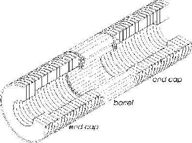
The barrel builds the center of the TRT. It is split into three times 32 modules, whereas each 1/32 of the circumference consists of three types of modules. They vary in size and number of straws. Each inner module (type 1) contains 329 straws, each middle module (type 2) contains 520 straws, and each outer module (type 3) contains 793 straws - see Figure 1.9.
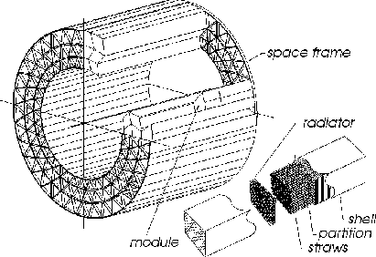 |
The straws inside the barrel are located parallel to the beam axis with a radial and azimuthal spacing of 6.8 mm between each two straws. The wire of each straw is electrically divided in two parts at the centre, thus giving two readout channels per straw. The barrel TRT consequently contains a total number of 52,544 straws with 105,088 electronic read-out channels.
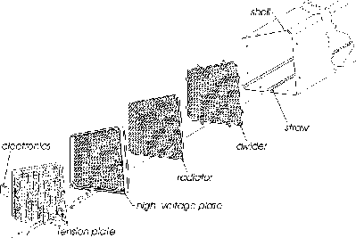
A module is housed in a carbon-fibre-reinforced plastic shell. Sets of printed-circuit boards build the end caps. On the outside, the "tension plate" holds the wires under a fixed tension and forms a part of the gas manifold. The tension plate connects to the front-end electronics and it touches a cooling plate in the inside of the module. The straws are glued to the high-voltage plate, which provides them with high voltage. The spaces between the straws are filled with radiators for transition radiation and with kapton sheets for the support of the straws - see Figure 1.10.
| end cap |
The sides of the TRT are built by the two end caps. One end cap is split into 18 modules - the wheels. Depending on the position, the structure of the wheels varies in size and number of straws. The first six wheels (type A) contain each 32 times 384 straws, the following eight wheels (type B) contain each 32 times 192 straws, and the last four wheels (type C) contain each 32 times 288 straws. Totally, one end cap contains 159,744 straws - see Figure 1.11.
 |
The straws inside the wheels are located perpendicular to the beam axis. This configuration and a different segmentation of the wheels allows an optimal three-dimensional resolution of the particle track.
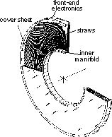 |
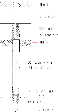
Three carbon-fibre rings provide together with the straws and printed-circuit boards (the active and the passive web) a self-supporting structure. Four planes of straws (wheel type A) are glued with fixation parts to the two inner rings (ring 1 and ring 2) - see Figure 1.12, and the two outer rings (ring 2 and ring 3) to the printed-circuit boards. The active web is a flexible-rigid printed-circuit board with an azimuthal extension of 1/16 of a wheel, which provides high-voltage and signal connections to the straws and the wires. The passive web is a rigid printed-circuit board without any traces.
 |
Two four-plane wheels build one eight-plane wheel or a halve wheel. A full wheel (of wheel type A) is made of 16 planes.
The gas manifold is closed at the top at ring 3, at the bottom of the straws with a aluminium shell (inner seal) and on the sides with copper-plated mylars.
| support |
The mechanical support of the barrel is provided by the reinforced shells themselves and by a carbon-fibre structure at the end of the barrel - the space frame. The wheels of the end cap are mounted inside an aluminium structure called the squirrel cage.
Before entering the front-end electronics, the input signal has to travel through a capacitor to decouple from the high voltage of the straw and through a protection circuit built of a serial resistor and a fast diode.
 |
| front-end electronics |
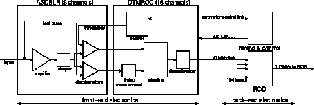
At the moment, the functions of the front-end electronics are performed by two separate chips. The ASDBLR (Amplifier-Shaper-Discriminator with BaseLine Restoration) is a full-custom, analogue, bipolar ASIC. It amplifies the straw signal, shapes the signal and removes the tail arising from the ion drift, and applies two thresholds to detect ionizing particles and transition- radiation X-rays.
The DTMROC (Drift-Time Measurement ReadOut Chip) is a CMOS digital chip. It obtains timing information to calculate the position of the impact of the particle into one straw, stores the information about timing and presence of the particles in a pipeline, extracts from the pipeline the information for each trigger signal, and controls the ASDBLR by setting the threshold levels.
The baseline is to integrate both chips into one design - the ASTRAL.
| back-end electronics |
The back-end electronics consists of two parts. A readout driver - the ROD - gathers the data from many channels, compresses and formats the information and sends it to a readout buffer (ROB) which is common to all the ATLAS sub-detectors. A second module - the TTC - is responsible to translate and to distribute the basic timing and trigger information from the central ATLAS TTC system for the front-end electronics and the ROD.
| services |
Several services are necessary to operate the TRT. The ASDBLR needs a bipolar supply of ± 3 V; the DTMROC needs a supply of + 5 V; and a high voltage of 1,600 V has to be maintained between the straw and its wire. A gas system has to provide the active gas - the Xe-gas mixture - and CO 2 for ventilation and cooling of the straws. An additional cooling system has to remove the heat produced by the electronics.
| February 9, 2000 - Martin Mandl | Copyright © CERN 2000 |